- Parent Category: Power Systems
- Category: Power Flow Test Systems
- Hits: 14773
10-Bus System (Glover's Book Test Case)
I. Introduction:
\(\bullet\) This 10 Bus Test Case is taken from the text book of Glover et al. [1]. It is given as a design project to the students.
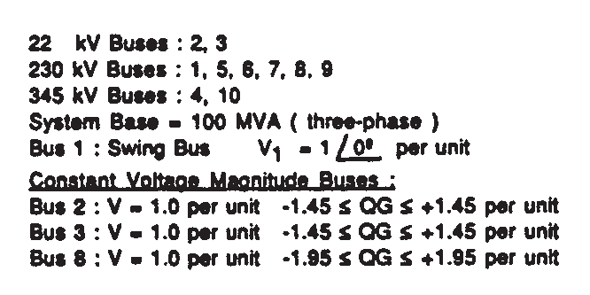
\(\bullet\) This test case consists of 10 buses, 7 generators, 5 transformers and 6 loads. Also, the system has three voltage levels as follows: 22 kV (2 buses), 230 kV (6 buses) and 345 kV (2 buses).
\(\bullet\) It is modeled under \(S_{base}=100 \ \text{MVA} \ (3\phi)\), and bus 1 is considered as a swing bus.
\(\bullet\) The required system data is as follows:
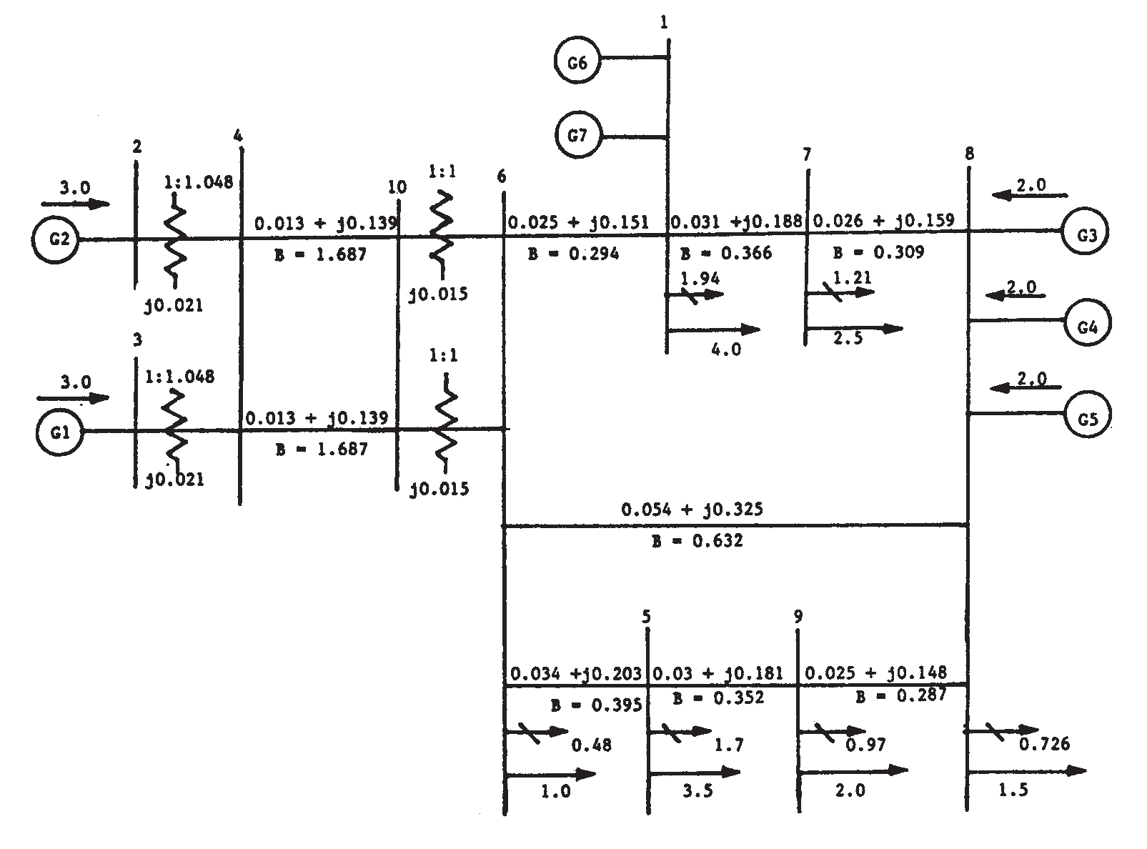
II. Single-Line Diagram:
\(\bullet\) The single-line diagram of the proposed system - as taken from the book - is shown below:
III. Files:
No file available yet...
IV. Citation Policy:
If you publish material based on databases obtained from this repository, then, in your acknowledgments, please note the assistance you received by using this repository. This will help others to obtain the same data sets and replicate your experiments. We suggest the following pseudo-APA reference format for referring to this repository:
Ali R. Al-Roomi (2015). Power Flow Test Systems Repository [https://al-roomi.org/power-flow]. Halifax, Nova Scotia, Canada: Dalhousie University, Electrical and Computer Engineering.
Here is a BiBTeX citation as well:
@MISC{Al-Roomi2015,
author = {Ali R. Al-Roomi},
title = {{Power Flow Test Systems Repository}},
year = {2015},
address = {Halifax, Nova Scotia, Canada},
institution = {Dalhousie University, Electrical and Computer Engineering},
url = {https://al-roomi.org/power-flow}
}
V. References:
[1] J. D. Glover, M. S. Sarma, and T. J. Overbye, Power System Analysis and Design, 5th ed. Stamford, CT: Cengage Learning, 2012.