
- Parent Category: Optimal Relay Coordination Test Systems
- Category: 15-Bus Systems
- Hits: 13736
15-Bus System (System I)
I. Introduction:
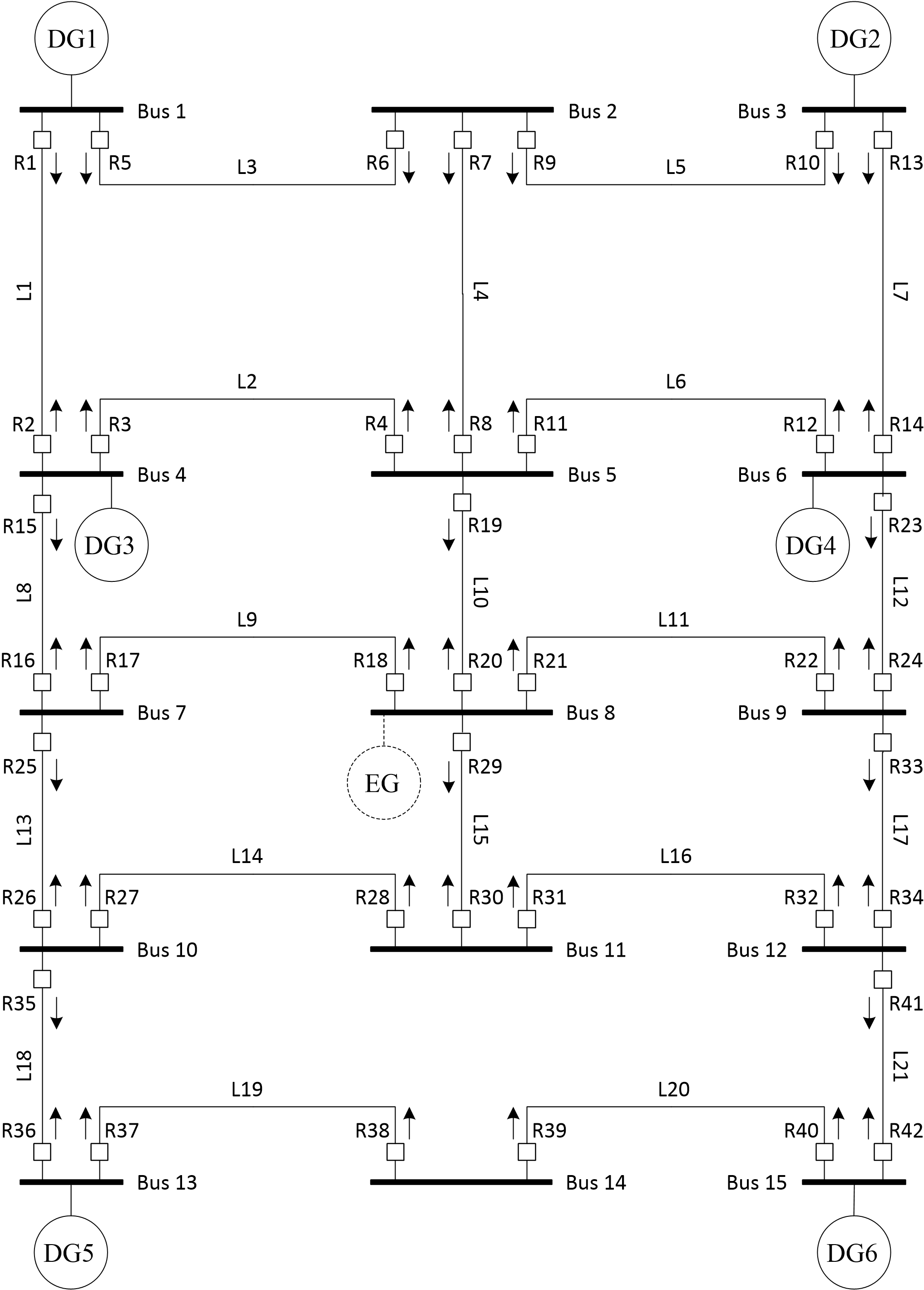
\(\bullet\) This system has \(3\phi\) close-in faults on all the lines, as shown in the figure given below.
\(\bullet\) The test system is presented as an example of highly penetrated/distributed generation (DG) distribution networks.
\(\bullet\) This system consists of 15 buses and 21 branches, and hence it has 42 directional overcurrent relays (DOCRs) and 82 primary/backup (P/B) relay pairs with 84 variables "if only one time-current characteristic curve (TCCC) is used for all DOCRs".
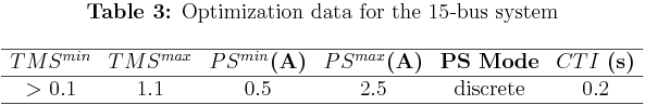
\(\bullet\) The total constraints are 250 and addressed as: 82 inequality constraints for P/B selectivity criteria, 42 inequality constraints for minimum allowable operating time, 42 inequality constraints for maximum allowable operating time, 42 side constraints for the time-multiplier setting (\(TMS)\) and 42 side constraints for the plug-setting (\(PS\)); where \(TMS\) is greater than 0.1, and \(PS\) is considered discrete in uniform steps of 0.5 A.
\(\bullet\) All the generators have the same ratings of 15 MVA, 20 kV, and a synchronous reactance of \(x=15\%\). Also, all the lines have the same impedance of \(Z=0.19+j0.46 \ \Omega/km\). Bus 8 is connected to an external grid modeled by 200 MVA short-circuit capacity. The fault analysis is done based on the IEC standard.
\(\bullet\) The listed relays' CT ratios (\(CTRs\)), P/B relay pairs, currents for the close-in \(3\phi\) faults, and the other important information about this test system all are available below (click on them for bigger size):

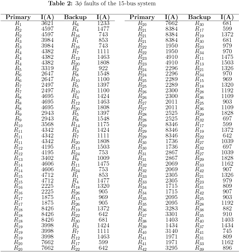
\(\bullet\) We have found some typo-errors on the short-circuit currents given in the original reference. These typo-errors have been addressed carefully and shown in Table 2. I want to thank Alexandre Akira Kida for the discussion about these corrections, and I think it is important to highlight them here too:
\(\bullet\) Based on the data given in the original, the relay \(R_{13}\) sees \(1503A\) when it is a backup for \(R_{12}\), and it sees \(1053A\) when it is a backup for \(R_{23}\). Because all the near-end/close-in faults are simulated by a bolted \(3\phi\) short-circuit on the bus \(x\), so the backup relay should see the same \(I_f\) for all the primary relays associated with. Therefore, the question is: which one should I select; \(1503A\) or \(1053A\)? By testing the results reported in the original reference, using our feasibility checking algorithms, we found that the value 1053 A gives some violations when it is used. Based on that, 1503A is selected instead.
\(\bullet\) Similar thing happens with \(R_{21}\) when it acts as a backup relay for the primary relays \(R_{24}\) and \(R_{33}\). With similar impedance (for all the branches), it is hard to select \(175A\) as the correct answer, especially if we see that all the other short-circuit currents are with high \(I_f\) values. Thus, \(1326A\) is selected as the correct value for the relay \(R_{21}\) when it acts as a backup relay.
II. Single-Line Diagram:
\(\bullet\) This single-line diagram was drawn by Ali R. Al-Roomi in Mar. 2014 and all the necessary data were coded in MATLAB m-files.
III. Files:
\(\bullet\) System DATA (MATLAB, m-file Format) [Download]
\(\bullet\) Results Tester (MATLAB, m-file Format) [Download]
IV. Citation Policy:
If you publish material based on databases obtained from this repository, then, in your acknowledgments, please note the assistance you received by using this repository. This will help others to obtain the same data sets and replicate your experiments. We suggest the following pseudo-APA reference format for referring to this repository:
Ali R. Al-Roomi (2015). Optimal Relay Coordination Test Systems Repository [https://www.al-roomi.org/coordination]. Halifax, Nova Scotia, Canada: Dalhousie University, Electrical and Computer Engineering.
Here is a BiBTeX citation as well:
@MISC{Al-Roomi2015,
author = {Ali R. Al-Roomi},
title = {{Optimal Relay Coordination Test Systems Repository}},
year = {2015},
address = {Halifax, Nova Scotia, Canada},
institution = {Dalhousie University, Electrical and Computer Engineering},
url = {https://www.al-roomi.org/coordination}
}
V. References:
[1] Ali R. Al-Roomi. Optimal Coordination of Power Protective Devices with Illustrative Examples. Hoboken, New Jersey: Wiley-IEEE Press, 2022.
 "Pin It")